Programming with Arduino IDE
This week we program the board we made in week 4. First, I tried to program it with arduino IDE. In order to do this for the ATtiny 44 chip, we need to install the ATtiny/ATmega package by going into preference and copy the link into additional board URLs and install the ATtiny board.
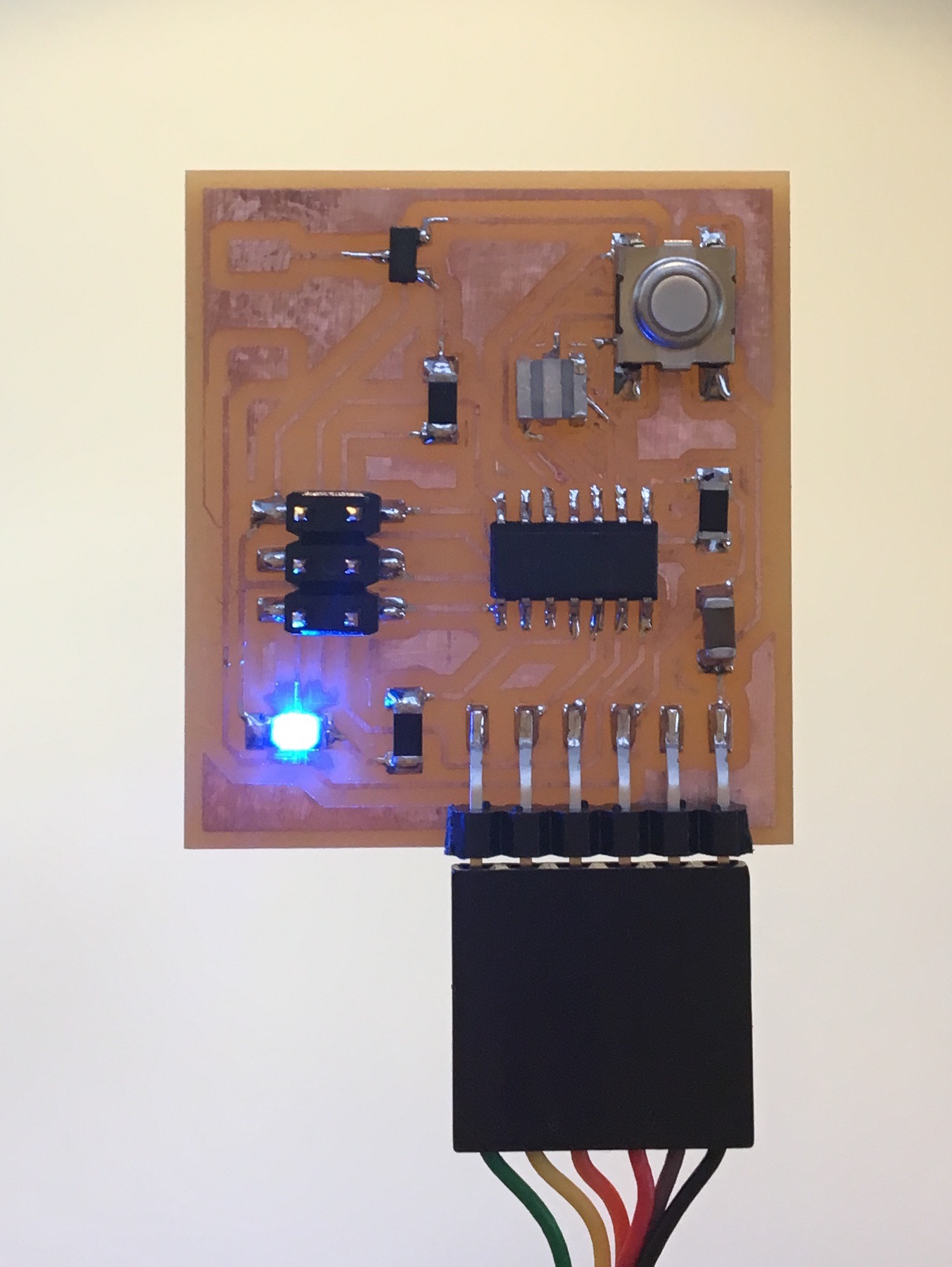
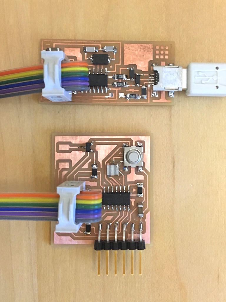
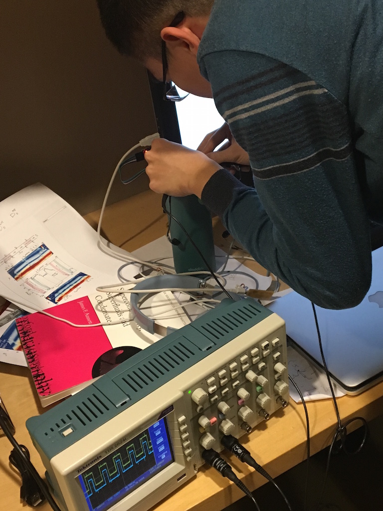
Then I connect the SPI cable between the echo board and FabISP with FabISP connect to computer USB and echo board connect to FTDI cable. Select the correct settings for the board in the tools manual and burn bootloader. Then I openned a blink example in arduino ,changed the pin number and uploaded the program. In the beginning the button was not working properly as I don't have a external pullup resistor for it. The input state is not quite defined when the button is not pressed and the LED just flickering because the pin is essentially floated. Then I turned on the internal pullup resistor and somehow the pin just pulled down to ground and the button doesn't do anything. After some trouble shooting, seems like I broke the pin somehow as it doesn't do what it suppose to do. I found an other free pin is working properly, so I desoldered the broken pin and linked the button to the working pin. Then I can use the button to turn on and off the LED.
Then I started to wonder if I can use other ways to program the board. I tried to use the serial interface with bootloader. The bootloader should be able to load program through FTDI cable. But it doesn't work, as it turns out the bootloader I burned is actually just the fuse, not the real bootloader.
Another way I tried is using a arduino as ISP, I connected the arduino with echo board by rainbow cable and loaded Arduino ISP program on arduino, then use arduino as programmer to load the program for echo board. Somehow this doesn't work neither.
Programming with GCC-AVRdude
Learning from the class, programming with C should be more efficient and probably will also give me more insight into how the programming work on the back. I definately like it better than arduino IDE, there was less problem uploading programs and less unexpected behaviors, also much more powerful. I started by the same blink LED task, and I manage to control the blink frequency with the button which I couldn't do with Arduino somehow though the code suppose to work. For the C coding we need a make file to compile the C code into hex code. The I used the following make file changed from Neil's example. Use 'make -f blink.make' to compile the file and 'make -f blink.make program-usbtiny' to upload the program.
	PROJECT="project name"
	SOURCES=$(PROJECT).c
	MMCU=attiny44
	F_CPU = 20000000

	CFLAGS=-mmcu=$(MMCU) -Wall -Os -DF_CPU=$(F_CPU)

	$(PROJECT).hex: $(PROJECT).out
		avr-objcopy -O ihex $(PROJECT).out $(PROJECT).c.hex;\
		avr-size --mcu=$(MMCU) --format=avr $(PROJECT).out

	$(PROJECT).out: $(SOURCES)
		avr-gcc $(CFLAGS) -I./ -o $(PROJECT).out $(SOURCES)

	program-usbtiny: $(PROJECT).hex
		avrdude -p t44 -P usb -c usbtiny -U flash:w:$(PROJECT).c.hex

	program-usbtiny-fuses: $(PROJECT).hex
		avrdude -p t44 -P usb -c usbtiny -U lfuse:w:0x5E:m
Blicking LED controlled by button
In this section, I demonstrate the program to control the blink frequency with the push of a button.
#include <avr/io.h>
#include <util/delay.h>
int main(void) {
// enable pull up resistor
DDRA = (1 << PA2);
PORTA = _BV(PA7);
//set clock multiplier to be 1
CLKPR = (1 << CLKPCE);
CLKPR = (0 << CLKPS3) | (0 << CLKPS2) | (0 << CLKPS1) | (0 << CLKPS0);
while (1) {
if ((PINA&(_BV(PA7)))==0){
PORTA |= (1 << PA2);
_delay_ms(100.0);
PORTA &= ~(1 << PA2);
_delay_ms(100.0);
// flash with 200ms period when button is pressed.
}else{
PORTA |= (1 << PA2);
_delay_ms(400);
PORTA &= ~(1 << PA2);
_delay_ms(400);
// flash with 800ms period when not pressed.
}}
return (0);
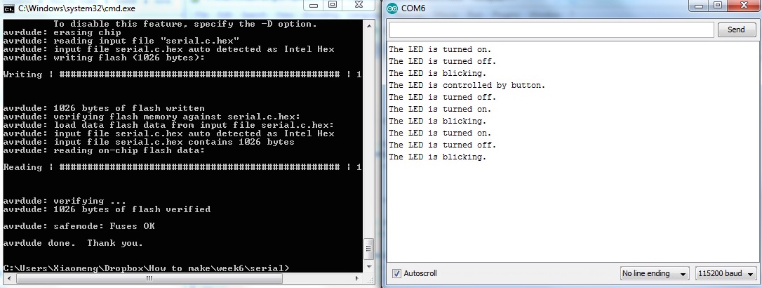
}Serial communication
Then I tried to build the LED controlled by the computer. I learned from online that ATmega328P have serial communication build-in, all you need to do is dump the data in a register. However, the ATtiny chip we use doesn't have that and requires coding to send and receive data. Fortunately, Neil already wrote the send and receive functions for the echo program which I can just borrow. I neglected those functions in my code below and only show the main function. I was able to control the LED with serial and set it into different mode by computer keys "0", "1", "2", "3".
int main(void) {
// set clock divider to /1
CLKPR = (1 << CLKPCE);
CLKPR = (0 << CLKPS3) | (0 << CLKPS2) | (0 << CLKPS1) | (0 << CLKPS0);
// initialize output pins
set(serial_port, serial_pin_out);
output(serial_direction, serial_pin_out);
//set up interrupt of counter 1
static char chr;
DDRA |= (1 << PA2);
PORTA = _BV(PA7);
TCCR1B |= (1 << WGM12); // CTC mode
TCCR1B |= (1 << CS12)|(1 << CS10); //1024 prescale
TIMSK1 |= (1 << OCIE1A); // compare A match interrupt enable
OCR1A = 5859; // compare value, 16bit
//set up interrupt for counter 0
TCCR0B |= (1 << CS00)|(1 << CS02); //1024 prescale
TIMSK0 |= (1 << TOIE0); // overflow enable
sei(); // interrupt enable
while (1) {
//get input and output corresponding message
get_char(&serial_pins, serial_pin_in, &chr);
if (chr == '0'){
put_string(&serial_port, serial_pin_out, "The LED is turned off.");
put_char(&serial_port, serial_pin_out, 10); // new line
LEDstatus = 0;
chr = 0;
}else if (chr == '1'){
put_string(&serial_port, serial_pin_out, "The LED is turned on.");
put_char(&serial_port, serial_pin_out, 10); // new line
LEDstatus = 1;
chr = 0;
}else if (chr == '2'){
put_string(&serial_port, serial_pin_out, "The LED is blicking.");
put_char(&serial_port, serial_pin_out, 10); // new line
LEDstatus = 2;
chr = 0;
}else if (chr == '3'){
put_string(&serial_port, serial_pin_out, "The LED is controlled by button.");
put_char(&serial_port, serial_pin_out, 10); // new line
LEDstatus = 3;
chr = 0;}
// turn on or off if 0 or 1 is pressed
if (LEDstatus == 0){PORTA &= ~(1 << PA2);}
else if (LEDstatus == 1){PORTA |= (1 << PA2);}
}
}
ISR(TIM1_COMPA_vect){
if (LEDstatus == 2){
// flash when 2 is pressed
PORTA ^= (1 << PA2);
}
}
ISR(TIM0_OVF_vect){
if (LEDstatus == 3){
//control by button is 3 is pressed
if ((PINA&(_BV(PA7)))==0){
PORTA |= (1 << PA2);
}else{
PORTA &= ~(1 << PA2);
}
}
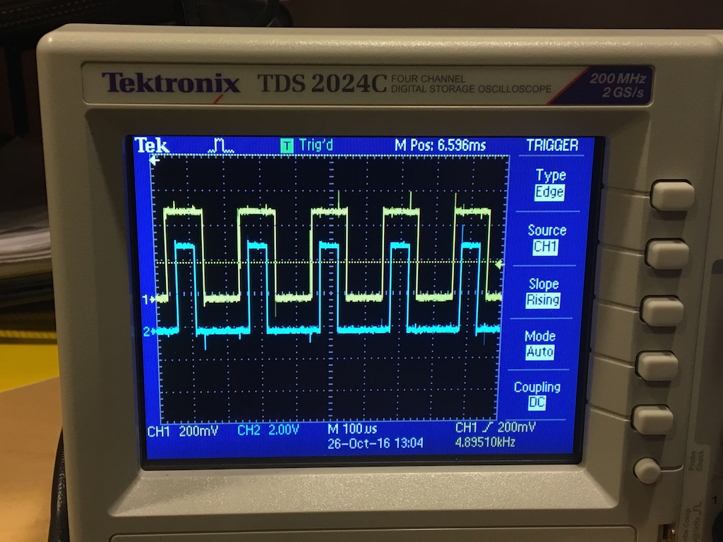
}PWM test with synchronization
Because my final project heavily replys on precise control of brushless motor, I worked to see if I can get the PWM to work. One concern I had was that I need three PWM signals to generate the three phases but each counter only have two compare value. This means I need to sync two counters together which I was not sure if possible. I wrote the following code showing not only two counters can be sync together, they can even has different UP limit which is compensated by a different clock prefactor. I am pretty happy with the result I got. On the osciloscope, you can see the two trace coming from two counters sync well with each other. The counter are operating in phase correct mode and use interrupt to triger the output value change. Also I don't need to stick with the PWM pins this way. Any pins can be setted inside the interrupt event.
	#include <avr/io.h>
	#include <util/delay.h>
	#include <avr/interrupt.h>
	int main(void) {

	   // set clock divider to /1
	   CLKPR = (1 << CLKPCE);
	   CLKPR = (0 << CLKPS3) | (0 << CLKPS2) | (0 << CLKPS1) | (0 << CLKPS0);

	   //enable output
	   DDRA = (1 << PA2) | (1 << PA3);
	   //enable pullup
	   PORTA = _BV(PA7);

	   // halt all timers;
	   GTCCR = (1 << TSM) | (1 << PSR10);
	   //set up timer 1
	   TCCR1A |= (1 << WGM11); // phase correct 10bits mode
	   TCCR1B |= (1 << WGM13);
	   TCCR1B |= (1 << CS10); //1 prescale
	   TIMSK1 |= (1 << OCIE1A); // compare A match interrupt enable
	   ICR1=2040; //8*255
	   OCR1A = 512; // compare value, 16bit, duty cycle 75%
	   //set up timer 0
	   TCCR0A |= (1 << WGM00); // phase correct 8bits mode
	   TCCR0B |= (1 << CS01); //1 prescale
	   TIMSK0 |= (1 << OCIE0A); // compare A match interrupt enable
	   OCR0A = 128; // compare value, 8bit, duty cycle 50%
	   //initialization
	   TCNT1= 0x0000;
	   TCNT0= 0x00;
	   PORTA &= ~(1 << PA2);
	   PORTA &= ~(1 << PA3);
	   GTCCR = 0;//release all timer

	   sei(); // interrupt enable

	   while (1) {
	   // duty cycle can be changed if wanted
	   // for example can tune the brightness of LED as following
	   /*  OCR1A = i*10;
		   if (i>200)
		   {i=1;}
	   i++;
	   _delay_ms(10); */
	   }
	}
	ISR(TIM1_COMPA_vect){
		PORTA ^= (1 << PA2);//switch PA2 for timer 1 interrupt
	}
	ISR(TIM0_COMPA_vect){
		PORTA ^= (1 << PA3);//switch PA3 for timer 0 interrupt
	}